Although you may use just NURB surfaces to design a boat, ProSurf and ProBasic behave more like general-purpose CAD programs, since they provide point, line, polyline, curve, and surface geometric entities. There is now a greater overlap between ProSurf and ProBasic and other CAD programs.
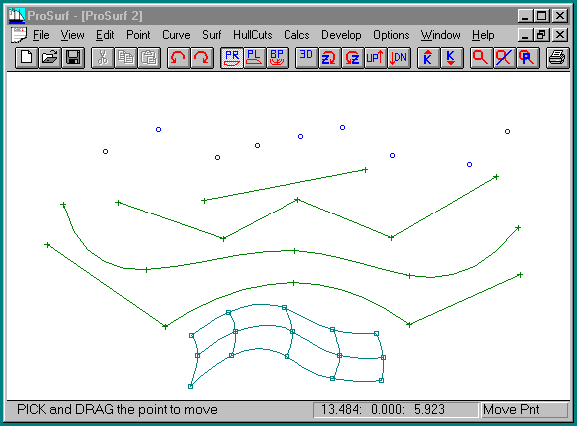
The following picture shows a sample of each type of entity.

Point Entities
At the top of the picture are point entities, shown by the small circles. One of their uses can be as "tick marks" which identify target shape positions for the boat.
Curve Entities
A curve entity, as defined in this program, can be a line, a polyline, a NURB curve, or a combination of the two. Examples of these entities are shown in the picture above. The "Curve-Add-Add Polyline" command allows you to add a line or polyline to the model. Each point of the polyline is entered by clicking the left mouse button, and the polyline is terminated by clicking the right mouse button. The "Curve-Add-Add Curve" command allows you to add a NURB curve to the model. Each point of the curve is entered by clicking the left mouse button and the curve is terminated by clicking the right mouse button.
These "curves" can be used for anything you like. For example, you might use the surfaces to define a 3D sailboat hull, but use the curve entities to define a 2D outboard profile of the rig and sails in profile view. Of course, you could define the rig and sails using 3D surfaces, but this extra work may not be necessary.
A combination polyline and NURB curve entity is obtained by using the "Curve-Knuckle Pnt" command. This command acts like a toggle switch which converts any interior polyline or curve point to or from a hard knuckle point. Therefore, any point of a polyline or curve can be converted to or from a knuckle point. This might seem odd since most CAD programs define separate curve and polyline entities. This technique, however is more powerful, since there is no difference between the two entities and you do not have to break and join different entities together. You can start by roughing out a shape usine a polyline and then convert portions into curves and then use the curvature curve indicator to fair the curve. For many CAD tasks, it might be easier to start in ProBasic or ProSurf, and then convert the entities over to your general-purpose CAD program.
Surface Entities
The surface entity is a NURB (Non-Uniform Rational B-spline) surface defined by a number of points at the intersections of the surface rows and columns. These defining points are displayed using a small squares. The NURB surface defines a complete, unique, rectangular-like, smooth, membrane, drawn using a number of rows and columns. Surfaces are added by defining their four corner points (with only two rows and two columns). You can then add in more rows or columns to add more flexibility and control points. The example in the picture above shows a surface with three rows and five columns.
ProSurf and ProBasic use controlling points which lie ON the NURB surface. (The same technique is used for NURB curves.). NURBS and B-splines are officially defined, however, using "vertex" points which do NOT lie on the surface, except for the four corner points. The original intent for B-splines was to provide a way to create a smooth surface that was "influenced" by these controlling vertices. By not requiring that the surface pass through the points, B-splines can create a relatively smooth surface even though the vertex points aren't perfectly positioned. The thought was that this was perfect for interactive design of free-form surfaces on a small computer screen. In practice, however, many users disliked the fact that the controlling vertices were floating off in space and that many programs connected the vertex points with a mesh which obscured the surface itself. In addition, most designers wanted very accurate shape control over the surface, because not just any smoothly curved shape will do. This accuracy requires direct control of the surface and some form of surface fairing technique.
When we started providing B-spline surface modeling in 1985, we decided to allow the user to control the shape of the B-spline surfaces using points on the surface. This had not been done by any other commercial CAD program in any industry. By eliminating the display of the vertex points, we cleaned up the display of the boat and gave the user more precise shape control over the boat, including the ability to input offsets and automatically fit surfaces to those offsets. Since we provided curvature curve display and control to use for fairing, the user had the best of both worlds: accurate shape control and detailed fairing.
With this new Windows version of the program, you can select from three ways to control the surface shape using points. You can use the traditional defining vertex points (floating off in space), or you can use either of two methods for defining points on the surface. Remember that we use industry standard NURB curves and surfaces. For every vertex point, there is an associated point on the surface. When you move the point on the surface, we calculate backwards to determine the associated move in the defining vertices.
We continue to follow the latest research papers on NURB surface techniques, plus add our own shaping and fairing techniques which are not found in any other CAD program.