[Home][What's New][Products][Contents][Feedback][Search]


Velocity Prediction Program


This module allows you to predict the speed of a sailboat for any wind speed and any point of sail.  It uses the same performance prediction technique as used by US Sailing's Lines Processing (LPP) and Velocity Prediction (VPP) programs.  This performance prediction method (used for the International Measurement System (IMS)) is based on MIT Report No. 78-11, "A Velocity Prediction Program for Ocean Racing Yachts".  Our module implements both the lines processing and velocity prediction parts of this performance model, along with extensive hydrostatic, stability, and race analysis tools, as described below.

Hydrostatic Analysis - Calculates 33 hydrostatic values, such as volume, center of buoyancy, wetted surface, and righting moment, for any draft, trim, and heel, with an optional balance for trim.  It will also print sectional areas, girths, and centroids.  Other options include conversion between drafts and freeboards, calculation of vertical center of gravity (VCG) from a righting moment, and calculation of draft and trim, given a displacement and longitudinal center of gravity (LCG).

Stability Analysis - Calculates the following values for heel angles between 0 and 180 degrees (balanced for trim): draft, trim, righting arm, displacement, righting moment, area under the righting arm curve, center of buoyancy, and distance of rail to waterline.  It also calculates the following overall values: rail under angle, limit of positive stability, Capsize Index, Size Index, Stability Index, positive righting arm area, negative righting arm area, and righting arm area ratio.  Ballast tank calculations can also be included.

Body Plan Output - Displays, prints, or plots the station definition body plan for the hull.

Lines Processing - Uses methods described in Report No. 78-11 to determine effective length, beam, and draft values from the station definition shape of the boat.  These effective size values are then used by the velocity prediction section to determine the performance of the vessel.  Effective size values are used to eliminate the dependency of the performance model on a very few point measurements.

Velocity Prediction - Calculates the velocity and heel angle for a sailboat for any wind speed and course.  Results can be tabulated or plotted in polar speed diagram form, and many intermediate and final values can be printed to evaluate all lift and drag forces.  Another option races the boat over a predefined or user-defined course and calculates the total elapsed time.  You can even enter a number of wind speeds and probabilities so that the program calculates an elapsed time which represents


This module does not calculate an IMS certificate.  It is intended as a performance prediction program which is integrated closely with the other design modules in the Nautilus Systemtm.  This means that you can you can quickly move between editing the shape of the hull and calculating its performance.

Used in conjunction with our Convert Hull and Lackenby Hull Variation modules, this module can perform a detailed performance analysis of a series of hull shape variations in a very short time.  Between these two modules, you can automatically and independently vary length, beam, draft, prismatic coefficient, and longitudinal center of buoyancy.  Add in the ability to vary any sail dimension for the velocity prediction section and you have the capability to optimize the performance of any design.


Pre/Post-Processor for
US Sailing's LPP/VPP


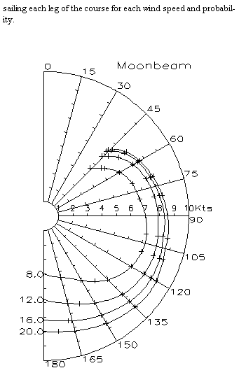
This module allows you to convert the Nautilus hull station definition to a format used by US Sailing's (formerly USYRU) Lines Processing Program (LPP) and Velocity Prediction Program (VPP) for sailboats.  This revised station definition is first used by US Sailing's Lines Processing Program to produce results read by US Sailing's Velocity Prediction Program.  The VPP then produces tabulated output of boat speed versus wind angle for a range of wind speeds.  The tabulated output can then be read by this program for plotting the polar speed curves for the boat, as shown in the example plot (US Sailing's VPP program does not do any plotting).

The LPP and VPP programs (available from US Sailing, P.O. Box 1260, 15 Maritime Dr.,  Portsmouth, Rhode Island, 02871 Tel: (401) 683-0800, Fax: (401) 683-0840) are used by US Sailing to calculate the International Measurement System (IMS) rating rule for sailboats.  It can also be used by designers to evaluate the speed and stability of a sailboat.  The purpose of this pre/post processor program is to provide a convenient connection to US Sailing's LPP/VPP programs from our hull design software and to provide a post-processing polar plot capability.


The tasks performed by this module are given below:


Pre LPP  -  This function converts a Nautilus station definition into an offsets file compatible with US Sailing's LPP program.  It also sets up a number of additional variables required by the ".OFF" offsets file format.


Post VPP -  This function takes the tabulated results from US Sailing's VPP program (stored in a file) and plots the polar speed diagram.


Read OFF -  This function allows you to convert hulls defined using an LPP offsets file (".OFF") into the Nautilus station definition form and stores the results in the vessel's database.


The general order of operations is as follows:

1.  Create a station definition of a hull using any of the programs provided by the Nautilus Systemtm.

2.  Use the Pre LPP function to convert this station definition into a legal LPP offsets file for input into the LPP program.

3.  Execute US Sailing's LPP program, using the LPP offsets file.

4.  Execute US Sailing's VPP program to produce a file containing tabulated data for various wind speeds and directions.

5.  Re-execute the pre/post processor and select the Post VPP option to produce a polar speed plot of the data produced by the VPP program.


Note - This pre/post processor program does not actually perform the lines processing and velocity prediction functions.  It is used only to connect our design programs to those provided by US Sailing.  If you want programs to perform the LPP and VPP functions, contact US Sailing or look at our all-in-one LPP/VPP program as described on a separate product page.


ABS Scantling Rules for
Offshore Racing Sailboats


This program performs all calculations described in the 1986 (including later updates) American Bureau of Shipping "Guide for Building and Classing Offshore Racing Yachts".  Specifically, it performs the following tasks:

o  Minimum keel bolt diameters
o  Minimum plating thicknesses
o  Minimum section modulus of internal components
o  Minimum rudder stock diameter
o  Minimum rudder bearing lengths
o  Minimum rudder bolt diameter
o  Maximum rudder horn stress

The following materials can be used:

o  Aluminum
o  Steel
o  Cold-molded wood
o  Wood carvel construction
o  FRP - single skin
o  FRP - sandwich construction

For plate and internal scantlings, the rule accounts for the following locations:

o  Above the waterline
o  Below the waterline
o  Deck
o  Bulkheads
o  Reinforced shell

The rudder calculations account for both spade and semi-spade rudders, along with solid and tubular stocks.

Program Operation


This program is fully integrated with The Nautilus System.  Up to 40 plates and structural members can be defined and saved in the boat's data base for future use. 

All input information for each calculation is displayed and entered on one screen, using a free-format input technique.  You simply move the cursor to each input field (in any order) and enter the information.  To calculate, you press one of the function keys, and the results are immediately displayed or printed.

The program is organized to match the ABS rule book, and uses all of the same terminology and variable names.  It has also been extensively tested and verified using both metric and English units.


Offshore Racing Yacht Rule


This guide has been established by The American Bureau of Shipping (ABS) to provide a sophisticated means for calculating the structural requirements of offshore racing yachts.  This rule has been embraced by the Offshore Racing Council (ORC) so that any boat racing under its rules must have its plans approved by ABS.

Although the guide was written for boats operating in tough, offshore conditions, it has been successfully used on a variety of boats, both power and sail.  At the very least, it provides a good check against other methods.


Summary of Results for Section 7: Plating

Daata File Name: ............................. abs2fps.abs
Units: ......................................  English

Plate Identification ........................    Case 2
Construction Type ...........................  STEEL_AL
Location of Plate ........................... BOT_SHELL
Minimum Ultimate Tensile Strength ...........  58000.00 psi
Spacing (s) .................................    16.00 in
Distance From Bow ...........................  11.2500 ft
Length of Long Edge of Panel (l) ............  33.0000 in
Curved Plate: Distance of Arc (A) ...........    2.6700 in

Section 7.1
Basic Head (Table 7.1) ......................  22.7925 ft
Multiplier for Basic Head (Table 7.1) .......    1.2000
Design Head (h) (Table 7.1) .................  27.3510 ft
Design Head Reduction Factor (F) ............    0.8849
Calculated Fh ...............................  24.2024
Limiting Value for Fh .......................  24.2024
Panel Aspect Ratio (l/s) ....................    2.0625
Correction Factor for Curved Plating (c) ....    0.8331
Limiting Value for Coefficient (c) ..........    0.8331
Coefficient (k) Varying With Panel AR .......    0.4952
Limiting Value for Coefficient (k) ..........    0.4952
Design Stress (Sigma_a) (Table 7.2) .........  34800.00 psi

Min Required Thickness of Plating (t) .......    0.1641 in

The Minimum Required Thickness Must Be Greater Than:
Minimum Thickness of Steel Plating ..........    0.1391 in
Minimum Thickness of Al Plating .............    0.1600 in


Spade Rudder: Forces & Moments  (Section 9.1.3)

Data File Name: .................................. abs4fps.abs
Units: ...........................................  English

Height (h)  (Figure 9.1) .........................  49.2000 in
Height (ha)  (Figure 9.1) ........................  12.0000 in
Height (hb)  (Figure 9.1) ........................  55.2000 in
Distance (xl)  (Figure 9.1) ......................  12.0000 in
Distance (lu)  (Figure 9.1) ......................  30.0000 in
Distance (ll)  (Figure 9.1) ......................  18.0000 in
Distance (l)  (Figure 9.1) .......................  24.0000 in
Maximim Width of Rudder (W) ......................    4.0000 in
Total Projected Area (A) .........................    8.5000 ft^2
Displacement of Hull .............................      2.00 tons
Lift Coefficient (C) .............................    1.5000

Factor N  (Section 9.1.3) ........................    1.0000
Total Force on the Rudder (P) ....................  1753.12 lb
Moment at Neck Bearing (Mn) ......................  50051.72 lb-in
Torque at Neck Bearing (Tn) ......................  5259.37 lb-in
Moment at Carrier Bearing (Mc) ...................      0.00 lb-in
Torque at Carrier Bearing (Tc) ...................  5259.37 lb-in


Send mail to shollist@newavesys.com with questions or comments about this web site.