This section discusses the shaping and fairing of generic surfaces. The next section shows how these techniques are applied to the shaping and fairing of boats.
This section assumes that you have gone through the material in the previous section on shaping and fairing curves, since many of the topics discussed there will be applied to surfaces.
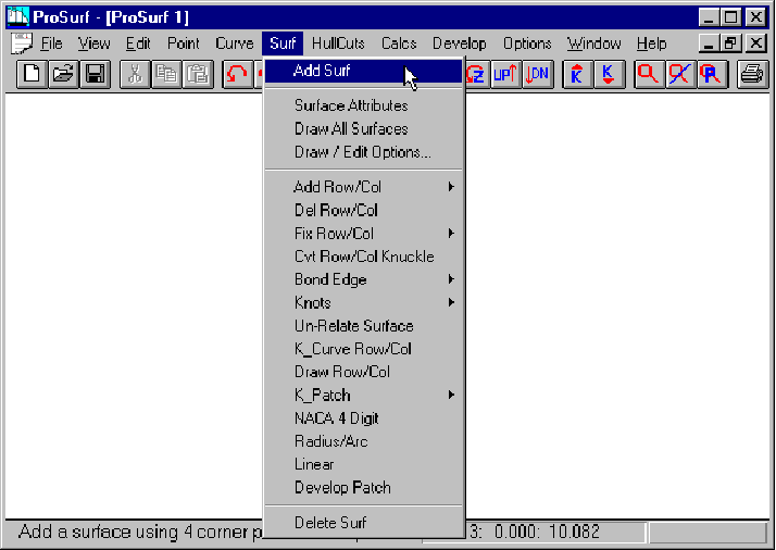
since we will be creating, shaping, and fairing surfaces, you will need to use the commands listed under the "Surf" pull-down list of commands, as shown in the figure above.
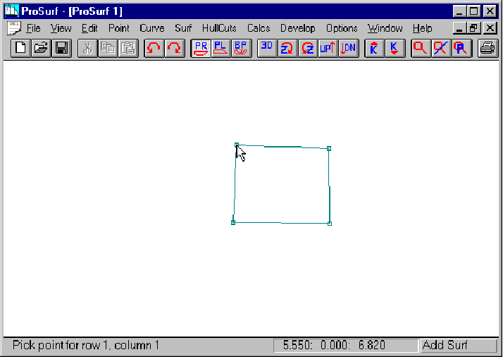
Start by adding a simple surface to a blank screen, as shown above.
![]() Select the "Add
Surf command in the Surf pull-down list of commands
Select the "Add
Surf command in the Surf pull-down list of commands
![]() Pick the four corners
of the surface - lower right, lower left, upper right, upper left
Pick the four corners
of the surface - lower right, lower left, upper right, upper left
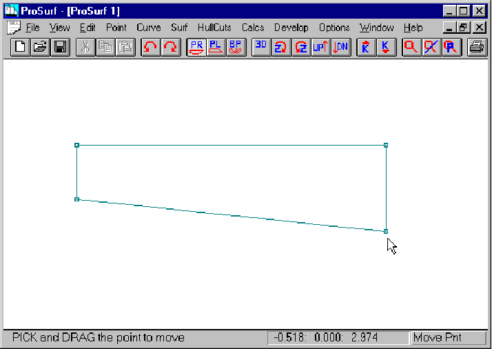
Change the shape to match the one shown above.
![]() Select the Move Point
command in the Edit pull-down list of commands
Select the Move Point
command in the Edit pull-down list of commands
![]() Move the point to get a
shape like the one shown above
Move the point to get a
shape like the one shown above
This is an arbitrary shape used only for demonstration.

Add one row and one column to the surface.
When you create a new NURB surface, you enter the corner points by rows. This defines the orientation of the surface relative to its rows and columns. In general, however, you do not have to worry about what are really rows and what are really columns of the surface. All of the surface commands work for either rows or columns. For the clarity of this tutorial, we will refer to horizontally oriented surface curves as rows and vertically oriented curves as columns, even though internally, the rows and columns might be oriented otherwise.
![]() Select the Surf-Add
Row/Col-Add Row/Col Angle command
Select the Surf-Add
Row/Col-Add Row/Col Angle command
![]() Add a row by splitting
the distance between the two existing rows. Pick a location along
one of the columns about half-way between the two rows.
Add a row by splitting
the distance between the two existing rows. Pick a location along
one of the columns about half-way between the two rows.
![]() Add a column by
splitting the distance between two existing columns. Pick a
location along one of the rows about half-way between the two
columns.
Add a column by
splitting the distance between two existing columns. Pick a
location along one of the rows about half-way between the two
columns.
As a rule, always try to add a row or column by splitting the difference between two existing rows or columns. You might end up with more row or columns than you think you might need, but the additional lines will help greatly with the shaping and fairing process.
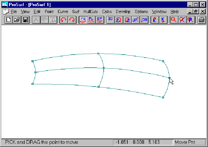
After you add one or two rows and columns, use the Move Point command to roughly shape the surface by eye. This is a much better approach than adding in a bunch of rows and columns before you begin any rough shaping of the surface. Don't worry yet, however, about fairing the surface with the k-curve. This will be done after a number of rows and columns have been added and the rough shaping has been completed.
![]() Select the Move Point
command from the Edit set of commands
Select the Move Point
command from the Edit set of commands
![]() Move the surface points
to get a shape like the one shown above.
Move the surface points
to get a shape like the one shown above.
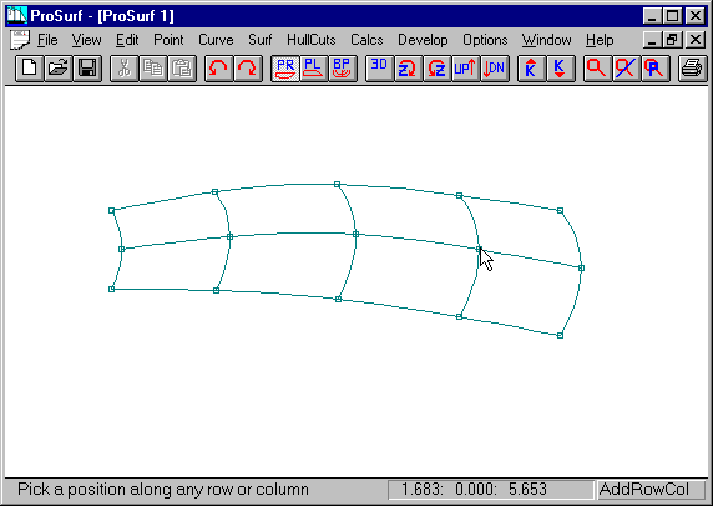
Now add two more columns to the surface, as shown above.
![]() Select the Surf-Add
Row/Col-Add Row/Col Angle command
Select the Surf-Add
Row/Col-Add Row/Col Angle command
![]() Add two more columns by
splitting the distance between two existing columns, like in the
picture above
Add two more columns by
splitting the distance between two existing columns, like in the
picture above
As mentioned above, it is always best to add new rows and columns by splitting the difference between two existing rows or columns. This keeps the rows and columns fairly evenly spaced, which will help the shaping and fairing process. If you don't keep the rows and columns evenly spaced, you might end up with a surface like the one below.

This surface was created by moving some of defining points to create unevenly-spaced rows and columns. This demonstrates some of the odd shapes that can happen when the row and column spacing is not even. Please note that the spacing does not have to be completely even. We generally suggest that the spacing between rows or columns not be anything greater than a 2:1 ratio of spacing. This means that if you have two columns one foot apart, then the "next" column should be no more that two feet further away, or less than ½ foot away. This spacing rule will be met if you always add rows and columns about one-half way between two existing rows or columns.
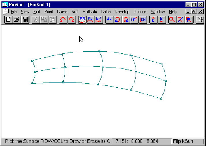
This picture shows the final, rough shape of the surface. (This is an arbitrary shape used only for this demonstration.)
![]() Select the Move Point
command
Select the Move Point
command
![]() Move the surface points
to match the surface in the picture above
Move the surface points
to match the surface in the picture above
![]() Only fair the surface
by eye using the Move Point command
Only fair the surface
by eye using the Move Point command
Now that the surface has been roughed into approximately the correct shape, the fairing can begin using the dynamic k-curve overlay technique.

This picture shows the surface with a k-curve turned on for the top row. (If you haven't done so already, please review the previous section on fairing curves before you continue. This section assumes that you understand some of the topics discussed there.)
![]() Select the Surf-K_Curve
Row/Col command
Select the Surf-K_Curve
Row/Col command
![]() Pick the top row of the
surface (pick the row somewhere away from a defining point)
Pick the top row of the
surface (pick the row somewhere away from a defining point)
![]() If the k-curve appears
too large (magnified), you may wish to use the K-Down toolbar
button to reduce the magnification of the k-curve
If the k-curve appears
too large (magnified), you may wish to use the K-Down toolbar
button to reduce the magnification of the k-curve
Note that your k-curve may not match the one shown above, because the k-curve is very sensitive to the shape of the surface.
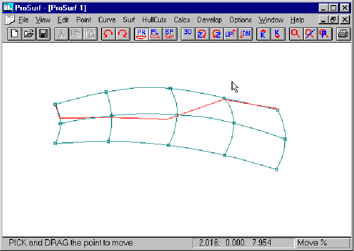
The goal of this tutorial is to fair this surface using the k-curves, starting with the top row. The shape we want for the rows is slightly curved on the left and fairly flat on the right. This is shown above in that the k-curve for the row is drawn away from the curve on the left and drawn on top of the row at the right (which means that it is flat in that area). Remember that you are the designer. Do not let the fairing process define the shape of the surface.
![]() Select the Move%
command
Select the Move%
command
![]() Move% the points in the
top row to achieve the k-curve shape shown above
Move% the points in the
top row to achieve the k-curve shape shown above

Now turn on the k-curve for the middle row and leave on the k-curve for the top row.
![]() Select the Surf-K_Curve
Row/Col command
Select the Surf-K_Curve
Row/Col command
![]() Pick the middle row of
the surface
Pick the middle row of
the surface
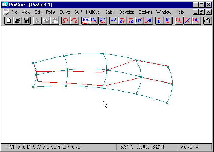
Use the Move% command to fair the shape of the middle row and use the top row k-curve shape as a guideline. You want to avoid the mistake of fairing the rows and columns of the surface without regard to the shapes of the surrounding rows and columns. The k-curve shapes of two consecutive rows or columns must be relatively the same.
![]() Select the Move%
command
Select the Move%
command
![]() Move% the points of the
middle row to get the shape (row and k-curve) shown above
Move% the points of the
middle row to get the shape (row and k-curve) shown above
Note that the shape of the middle row k-curve is very close to the shape of the top row k-curve.
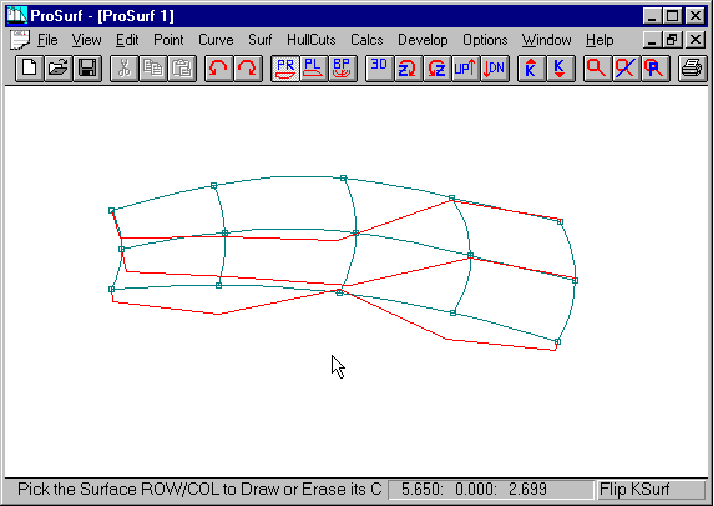
Now turn on the k-curve of the bottom row and leave on the k-curves for the other two rows. The screen is starting to get a little cluttered, but the different color for the k-curves help them stand out.
![]() Select the Surf-K_Curve
Row/Col command
Select the Surf-K_Curve
Row/Col command
![]() Pick the bottom row of
the surface
Pick the bottom row of
the surface

Use the Move% command to fair the shape of the bottom row and use the middle and top row k-curve shapes as a guideline. Follow the same process as before to shape and fair the bottom row.
![]() Select the Move%
command
Select the Move%
command
![]() Move% the points of the
botom row to get the shape (row and k-curve) shown above
Move% the points of the
botom row to get the shape (row and k-curve) shown above
Note that the shape of the bottom row k-curve is very close to the shape of the upper row k-curves.
Now that the rows have been faired, you can turn off their display.
![]() Select the Surf-K_Curve
Row/Col command
Select the Surf-K_Curve
Row/Col command
![]() Pick all three rows to
turn off the k-curve display
Pick all three rows to
turn off the k-curve display
Note that the same command is used to turn on and off the display of the curvature curve lines. That is why it is called a "toggle".
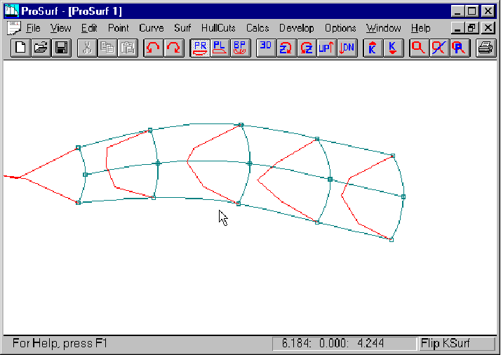
Fairing the columns is not as important, since they are defined with only three points, and are guaranteed to be fair automatically. However, you want to make sure that all columns have the same general k-curve shape. Remember that you have to both fair the k-curves and make sure that consecutive row or column k-curves have roughly the same shape, or at least, make sure that there is a reasonable change in shape from one k-curve to another.
![]() Select the Surf-K_Curve
Row/Col command
Select the Surf-K_Curve
Row/Col command
![]() Pick all of the columns
to turn on their k-curves, as shown above
Pick all of the columns
to turn on their k-curves, as shown above
![]() Use the K-Down toolbar
command to reduce the k-curve magnification, if necessary
Use the K-Down toolbar
command to reduce the k-curve magnification, if necessary
Note that the k-curves are all relatively fair, but their shapes do not match very well.
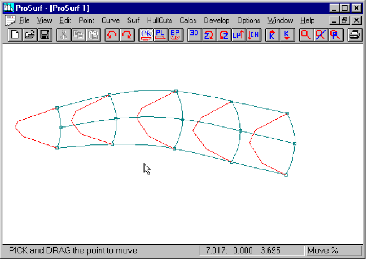
This picture shows the results of moving points on the middle row to make sure that all k-curves have the same general shape. Since all of the columns are part of the same surface, you want them all to have the same characteristics. This doesn't mean that the surface cannot change its shape dramatically from one end to the other. It just means that you must pay attention to the change in k-curve shape from one row or column to another.
![]() Select the Move%
command
Select the Move%
command
![]() Move% the points on the
middle row to match up the shapes of all of the column k-curves. Tip:
If you move the points in a direction tangent to the middle row,
you will not (greatly) affect the fairness of the rows
themselves.
Move% the points on the
middle row to match up the shapes of all of the column k-curves. Tip:
If you move the points in a direction tangent to the middle row,
you will not (greatly) affect the fairness of the rows
themselves.
![]() Move% the points to get
the shape of the surface shown above
Move% the points to get
the shape of the surface shown above
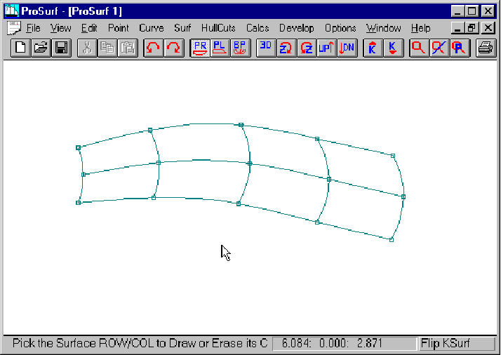
This picture shows the final surface with all of the k-curves turned off.
![]() Select the Surf-K_Curve
Row/Col command
Select the Surf-K_Curve
Row/Col command
![]() Pick all of the columns
to turn off the display of the k-curves
Pick all of the columns
to turn off the display of the k-curves
Conclusion
This was a brief introduction to the process of fairing surfaces. It was not very realistic in that it was all done in one view and the surface is perfectly flat. The next section more realistically describes the shaping and fairing process for a complete 3D hull surface using multiple views.
The following are some key items to remember.
1. Try to evenly space the rows and columns: remember the 2:1 spacing ratio limit
2. Perform rough shaping with the Move Point command after adding-in each row or column
3. Fair the surface by fairing the rows and columns
4. Turn on multiple k-curves and make sure that their shapes change gradually from one row or column to another.