CreateBoat Example
Stephen M. Hollister
New Wave Systems, Inc.
www.newavesys.com
This is a beginners
tutorial to introduce you the basic functions and features of our ProChine
program (also applies to ProBasic and ProSurf). This can be the first tutorial
you see before using the program for the first time. We will give you
step-by-step instructions that will allow you to try out the program and see
what it can do. We assume that you are
a little bit familiar with how to use the computer and how Windows programs
work in general.
Start by double-clicking
the ProChine (or ProBasic or ProSurf) icon on your Windows desktop. You should
see the following screen with four blank windows (after the startup information
screen has been shown).
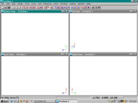
Each window will show a
different view of the boat: side (back) or profile view, top (or bottom) or
plan view, right or section or bodyplan view, and finally the 3D or perspective
view. These views sometimes confuse people since the profile view of the boat
is called either the front or back view, depending on which direction the bow
of the boat on the screen. Also, the plan view is called the “bottom” view (as
opposed to the top view) because we like to keep the bow of the boat pointing
to the right. (Have you ever noticed that boats only seem to go to the right?)
Don’t get too confused by the labels of the views. Part of our view labeling
scheme is based on what the general purpose CAD programs use.
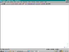
The next change I want
to make is to eliminate 3 of the 4 view windows. Some people like to see all 4
views of the model at one time, but I like to see just one view, but at maximum
size. I did this by clicking on the ‘X’ in 3 of the 4 windows. Then I maximized
the remaining window. If I want to see a different view than the one I have on
the screen, all I have to do is pick the appropriate button on the toolbar.
Speaking of the toolbar, it is shown below and some of the functions are
explained.
![]()
As you can see, it looks
like a standard toolbar with the command or function pull-down menus located at
the top. All of the file and print options work like any other Windows program
so they will not be discussed here. If you want a brief description of the
toolbar functions, just hold the cursor over the toolbar “button” and a label
will be displayed.
The most important
command on the toolbar is the counter-clockwise arrow, which is the Undo
command. Anytime you change the geometry of the boat and wish to undo the
change, just pick on this button once. You can go back up to 25 steps and you
can show a list of the previous Undo commands using a command in the View list
of commands. The ‘H’ buttons with the circular arrows are for hiding and
un-hiding geometry on the screen. This is important when your boat gets
complicated and you want to temporarily hide portions so that you can see what
you are doing. The 4-direction arrow button is selected when you want to move
the “edit” points that control the shape of the boat (Move Point). This is the
most common command you will use to change the shape of your boat.
Please note that most of
the commands in the program are “mode” commands. This means that the command
you picked will stay “ON” until you select another command. This means that if
you pick the Move Point command, you can continue to move any point on the
model until you pick another command.
You do not have to first select the geometry or entity before you can
edit its shape.
The tool bar buttons
that look like (or at least are supposed to look like) a boat’s profile, a
boat’s top view, and a boat’s section view are used to change the view of the
boat in the current window. The 3D button puts the current view into the 3D
perspective view. The 3D button is followed by 4 buttons that will change the
view of the boat in the 3D view; either up or down or rotate left or rotate
right. If you switched the program’s display to just one window, you will use
these buttons to change the current window to display that view.
The ‘K’ buttons are use
to display and control the curvature or “K-curve” on the boat’s curves and they
are used to magnify the fairness of the hull.
You will have to see the special tutorial on fairing and smoothing to
find out more about these commands.
However, the toolbar
buttons that look like hand-held magnifying glasses are important. The one that
looks like a plain magnifying glass is used to “zoom” in on a portion of the
window that you are interested in. It works just like many other CAD programs
in that you will press the left mouse button and drag a zoom box to define the
area you wish to enlarge. The magnifying glass with the line through it is used
to reset the view. It will resize the display to maximize the view of the boat
in the window. You will need to use this command many times.
OK, let’s get started
the easy way by using the CreateBoat command in the program. This command,
located in the File set of pull-down commands displays the following dialog box
and allows you to define a starting shape for a boat that uses your own
principal dimensions. Go ahead and select this command and you should see this
input dialog box.
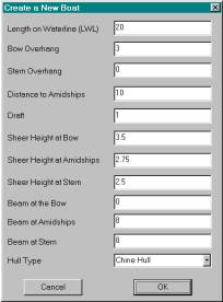
Note that the values are
filled in already. This is done for two reasons. One, so you can see what an
example boat’s values look like and two, so you can pick the OK button and
create a sample boat without having to come up with your own values. There are
many times you might want to quickly create a test boat so that you can try out
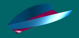
some things… like now. So, pick the OK button and you will see the following
screen if your current view is the profile view of the boat. This command
creates a starting shape of the boat using 3 NURB surfaces: one for the bottom
surface below the chine, one for above the chine and one for the deck.
Initially, the deck surface is turned off. Initially, there is no transom
defined. That can be added later, if needed. This is a considered to be a 3D
geometric surface model of the boat.
The first thing I want
you to do is to use the toolbar buttons to look at all of the 4 views of the
boat.
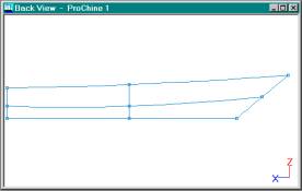
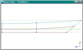
When you pick the side
view toolbar button, you should see this view.
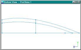
When you pick the top
(or bottom) or plan view toolbar button, you should see this view. If you want
to be picky, then this is a view of the bottom of the boat and what is drawn is
the starboard half of the boat. Note that the program assumes that the boat is
symmetrical about the centerline and all you have to do is to design one-half
of the boat.
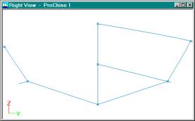
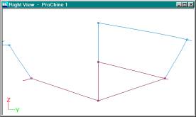
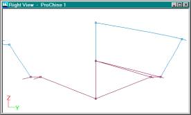
When you pick the right
or section view toolbar button, then you will see this view. This may look
rather odd, but it is a common sight for boat designers or naval architects.
The traditional display of a boat in cross-section or bodyplan view shows the
forward sections (in front of amidships) on the right of the centerline and the
aft sections (aft of amidships) on the left of the centerline. The reason this
is done is to clean up the display of the sections so that the aft sections
(stations or frames, if you prefer) do not overlay on top of the forward
sections. The bodyplan view takes a little bit of time to get used to, but it
does clean up the view. Perhaps not too much for this simple boat, but for
complex shapes, it can make a big difference. You can, however, turn this
“flip” option off or adjust exactly where along the length of the boat you can
flip the sections from the right to the left.
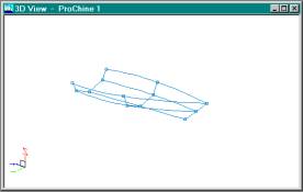
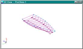
This view is displayed
when you pick the “3D” button on the toolbar. The program will display both
halves of the hull for viewing. Try using the “Z” rotate buttons and the “Up”
and “Dn” buttons to rotate the boat left and right and up and down.

Next, go to the “View”
set of pull-down commands and select the Render View-Open Render View command.
You should see something like this. You can also use the rotate buttons to
change the angle of the boat in this view. Note that you cannot edit the shape
of the boat in this view – perhaps in a future version.
[Note that we use the
OpenGL render display commands provided with all Windows systems. We have noted
that in some systems, this display might look incorrect or extra jagged. If so,
then go to the View-Render View-Screen Options dialog box and make sure that
the “Nurb Polygon Tolerance” input field is set to 15. If this doesn’t help,
then feel free to contact us.]
To leave the Render View
of the boat, just pick the ‘X’ in the corner of the window. You can re-display
the view at any time using the render command. For the next part of the
tutorial, you want to turn off the render display.
If you want to change
the color or some other attribute of a surface, all you need to do is to use
the “right” mouse button and click on any curve that represents any one of the
surfaces. The following surface attribute dialog box will be displayed.
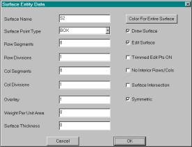
I will not take the time
to explain all of these options, but they are used to control the options for
the surface you picked. If you pick the “Color” button, you will see a standard
Windows color selection dialog box where you can select a standard color or
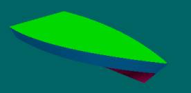
create a unique color yourself. For this tutorial, I picked the bottom surface
and changed it to a burgundy-like color.

This is what it looked
like after going back to the Render View display. Remember, so far, we have not
changed the shape of the boat yet.
Before we go on, pick
the ‘X’ for this display and go back to one of the standard views of the boat.
We will now define a set of stations, buttocks, and waterlines for the
boat. This is done with the
PlaneCuts-Initialize Lines command. (Select the PlaneCuts pull-down menu and
select the Initialize Lines command.) You should see the following dialog box.
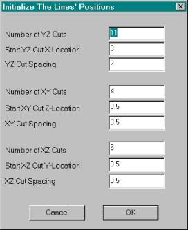
This dialog box allows
you to define a set of stations, waterlines, and buttocks that you want to use
for the boat. These lines will form a starting set of lines for the boat that you
can add to or subtract from. Do not feel that you are stuck with this starting
set of lines. Often times, a designer might use a certain set of stations
during the design of the boat, but switch to a different set of “frames” for
building purposes. You can also add or delete lines from this list at any time.
For those getting a
little bit confused, keep in mind that our program uses NURB surface “rows” and
“columns” to define the shapes of all surfaces. The columns are kind of like
stations and the rows are kind of like diagonals. One of the biggest changes
from traditional hand drafting is the use of these NURB surfaces where you
control the shape with “rows” and “columns” and NOT stations, waterlines, and
buttocks. You can, however, display any of these traditional lines during the
editing process. For example, you can
see a waterline change shape while you edit a surface row or column, but you
cannot directly edit the shape of the waterline itself. The benefit of this
technique, however, is that you do not have to make sure that the three views
of the boat match up. The NURB surfaces are guaranteed to match up in all three
views.
Anyway, just pick the OK
button to accept the default lines for the default boat. [The default boat and
lines make it easy to play around with the program.] Next, select the
PlaneCuts-Display Lines-All Lines ON command to show the lines on the boat. For
the profile view, you should see the following.
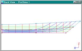
You can switch to the
other views to see the lines in those views. The green lines are the
waterlines, the red are the stations, and the blue are the buttocks.
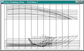
To see this traditional
lines view of the boat, select the View-Lines View command. Note that at any
time, you can print the current view using the File-Print command. The default
is to scale the view to maximize its display on your printer. You can also
control the scale factor of the output and plot all the way up to full size.
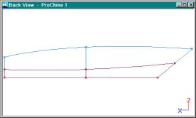
Before I start to edit
the shape of the boat, I’m going to turn off the automatic display of the lines
(PlaneCuts-Display Lines-All Lines OFF command) and display one of the 3
standard views of the hull. For this example, I will use the profile view of
the boat.
To begin editing the
shape, you need to select the Move Point button on the toolbar. This is the
button showing the four arrows pointing in different directions. I call this
the “rough” shaping part of the design process. This is not the time yet for
detailed shaping and fairing or smoothing.
Once the Move Point
command has been selected, you can select and drag any edit point on the boat.
An edit point is defined by a little square located at the intersections of all
curves (rows and columns) on the surface. Notice that each surface of the hull
is defined with only two rows (the top surface has the sheer and chine rows and
the bottom surface has the chine and profile or fairbody rows). Also note that
each surface is made up of only three columns (one at the bow, one at amidships
and one at the transom). For the NURB surfaces that are used to define these
surfaces, the rows and columns that define their shapes can be moved into any
position you want. However, it is best if you try to follow some basic rules
and terminology. For example, we call the curves that go along the length of
the boat the “rows” and the curves that go vertically the “columns”. These
definitions help us explain how to use the program. In addition, it is best if
you try to use the fewest rows and columns as possible (this makes it easier to
smooth or fair the hull) and try to keep a relatively even spacing of the rows
and columns (this avoids unwanted wiggles or bumps in the surface).
The CreateBoat command
creates a boat with the desired principal dimensions using the fewest rows and
columns as possible. The initial shape of the boat is very simple, but the
expectation is that you will be adding in more rows and columns to create your
desired shape. (There is another tutorial that goes into detail about the whole
hull design, shaping, and fairing process.)
OK, where were we? Oh
yes, Move Point. Once this command is selected, you can proceed to grab and
drag any point on the model. (Remember the Undo command if you make any
mistakes!) In the example below, I grabbed the amidships sheer edit point and
moved it much higher. Keep in mind that these are NURB surfaces and that any
change in shape in one direction affects the shape in all directions. This
means that the 3D model remains complete and exact.
Note that if you move an
edit point on the chine curve (common to both surfaces) then both of the
surfaces move together and do not split apart. Of course (!) you say? Well, you
might be surprised to find that many (most?) CAD programs can’t move both
surfaces at the same time!?! Our program sets up a geometric relationship
between the two surfaces so that if you move a common point on both surfaces,
then both surfaces move at the same time.
Also, remember that you do not have to “select” any geometry (like in
many CAD programs) before you can edit its shape. Once you select the Move
Point command, you can proceed to (and
continue to) move any edit point on the model.
Once you move a point on
the hull, try looking at the hull in all views, including the Render View, as
shown below.
The Render View should
reinforce the concept that the NURB surfaces are true 3D surfaces that
completely define the shape of the hull.
All you have to do is to shape and fair the hull surface.
I won’t go into the
whole shape designing process here since it is covered in detail in another
tutorial. I will just say that the process involves two phases: one is the
rough fairing portion that uses the Move Point command and the commands to add
additional rows and columns in the boat. The second phase involves using the
curvature curves (K-curves) to do the final fairing or smoothing of the boat.
Before I continue, I
want to Undo the change to the sheer curve that I just made.
What I do want to show
here, however, is the process of adding another chine to the boat. (I hope you
didn’t wait until this point to find out that you are not stuck with the single
chine that CreateBoat gives you.) The first thing you should do is to display
the “Right” or section or bodyplan view of the boat on the screen.
For this example, I want
to add a horizontal chine step to the boat. This can be done with just a few
commands. The first one is the Surf-Add Row/Col-Add Row/Col Knuckle command.
This command allows you to add a chine “row” to the hull in one step. What it
will actually do is to split a surface into two surfaces at your picked point.
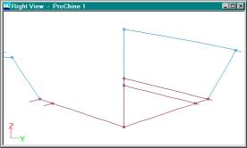
After you select this
command, position the cursor on the amidships column (station, if you want),
just below the chine and click the left mouse button. You should see something
like this above. The program has split the bottom surface into two portions at
the newly inserted row.
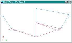
The next step is to
merge the forward end of the new chine step row with the forward end of the
original chine. This is done with the Edit-Merge Pnt To Pnt command. When you
pick this command, it will display the following on the status line:
“Pick the point to
merge”
Pick the forward-most
edit point on the new chine row.
The next message will
be:
“Pick the merge to
point”
Pick the forward-most
edit point on the old chine row. Now the two points are tied together and you
can use the Move Point command to move them both at the same time. The points
will stay merged together unless you specifically un-merge them.
Since I want to have a
perfectly horizontal chine step, I want to move the inside chine edit points to
have the same height or ‘Z’ value as their associated outside chine points.
There is a quick way to do this with the Edit-Match Pnt-Z Match command. This
command allows you to set the first picked edit point to the same ‘Z’ value as
the second picked point. The picture above shows the result of using this
command on the middle and aft inner chine edit points.

Adding a new chine takes
only a minute or two. The Render View above shows the result of adding a
horizontal step into the boat. Of course, I really needed to talk about
creating the proper shape and width of the step, but this tutorial is getting
to be long enough. In real life, one would probably spend quite a bit of time
on the hull shape before adding the inside chine step. It is much easier to
shape the hull without the inside chine than with the inside chine.
As you design the boat,
you might want to see a grid that defines the original principal dimensions
that you entered in the CreateBoat dialog box. We call these the “target”
values since those are the numbers you entered, but the program allows you to
change the shape to any size that you want. This is done by setting a value in
the Options-Display Options dialog box, as shown below.
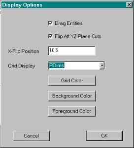
To draw the principal
dimensions on each view, change the Grid Display menu to “Pdims” for principal
dimensions. After you pick the OK button, you will see something like what is
shown below.
The green line is the
target waterline. Of course, you don’t know where it will float, but many
designers like to see where they “hope” it will float. If you want to change
any of these target dimensions, you can do so in the File-Design Data dialog
box.
At any time during the
design process, you can calculate the hydrostatics, stability and resistance of
the boat. This will allow you change the shape of the boat early in the design
process to make sure that the target weight or displacement of the boat matches
the desired waterline location.
The hydrostatics are
calculated using the defined (PlaneCut) stations, so you must make sure that
there are “enough” stations (10-25) defined along the length of the boat. Also,
the program does not require you to close off all portions of the hull with
surfaces. For example, this boat does not have a deck or a transom. The program
will, however, close off the deck when creating the stations to use for the
calculations. Since this is not an exact process (the program may have to make
some educated guesses), then you must check to see if the stations that will be
used for the calculations look OK. This is done with the Calcs-Hydro-Draw
Stations command. When you pick this command, you will see the stations that
will be used for the hydrostatics calculations drawn in purple, as shown below.
You can rotate the boat
and zoom in to make sure that these stations look correct and are located from
the front of the boat all the way to the transom. Remember that the
calculations are done using these stations, so, if they look good and they
cover the full length of the hull, then you know the calculations will be
accurate. (Note that our calculation routines have been developed over 25+
years and have been tested on boats of all sizes and shapes.)
After you check out the
stations and they look OK, select the Calc-Hydro-Hydro Input+Calc command to
display the Hydrostatics Input dialog screen shown below.
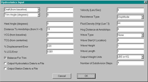
I won’t explain all of
the options since our goal is to show you just a little bit about how the program
works. There are four different ways to
do the calculation. The first is to enter a draft (distance from the baseline
at amidships) and a trim angle. The second is to enter a draft and LCG
(longitudinal center of gravity). The third is to enter a displacement and trim
angle. The fourth is to enter a displacement and LCG. In the early stages of
design, most designers use the target draft and a trim of zero and that is what
is filled in here in the dialog box. Later in the design process, after you
have put together a detailed weight and center of gravity study, you will
probably enter the displacement, LCG, and VCG values and see where the program
says the boat will float.
Just for the sake of the
example, use the existing input values and just pick the OK button. You should
see something like what is shown below (a partial listing of the results).
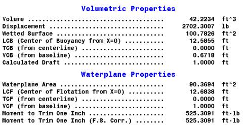
There are actually over
35 different values that are calculated and displayed. You can even output many
different sectional area data values that you can import into a spreadsheet for
further analysis. You might notice a number of calculated values that are
unfamiliar, like “Moment to Trim One Inch”.
Since we are doing the calculations, we figured that we should provide
as many values as possible, even if they are useful for only a few designers.
Also note that if you enter a heel angle, the
program will first do the calculation in the upright condition and then use the
calculated displacement and LCB to determine where the boat will float when it
is heeled over. In other words, the program will heel the boat to the desired
angle and then automatically sink and trim the boat to find the balance
condition that matches the upright condition displacement and LCB.
The program also
provides four different types of resistance calculations, but you have to enter
a target speed or velocity. One type of resistance is for canoes and kayaks
(Kaper), one is for sailboats (Delft), one is for planning powerboats in the
pre-planing condition (DispMode), and one is for large ships (Holtrop). Keep in
mind that these are “empirical” calculations whose results may not be perfectly
accurate, since they are trying to determine a very complicated result. They
are actually better at comparing boat ‘A’ with boat ‘B’ (a relative comparison),
rather determining the exact resistance of the boat. Also note that these resistance calculations are based on the
values of the boat at the current hydrostatic balance condition, using
calculated values like the waterline length, displacement, wetted surface and
half angle of entrance of the waterline.
After looking at the
hydrostatics values, you can select another hull view toolbar button to change
the view.
The next big area of the
program to investigate is plate development or layout. For many, the ability to
plot or cut full-size the frames and plates is the main reason for using this
program. If you don’t know too much
about plate development and layout, I would suggest that you read our other
article on this subject. It talks about the difference between developable,
expandable, and buildable. Many hulls may not be perfectly developable, but
they are buildable.
This program gives you
two ways to create and check for developable surfaces. One way, familiar to
many, is to use “ruling lines” that connect two curves, such as a chine curve
and a sheer curve. The ruling line method is described in another one of our
tutorials and will not be discussed here. Here, we will look at the process of
unwrapping or developing a surface and do some checks to see how close a
surface is to being perfectly developable.
The program will try to
unwrap or flatten any surface. All you have to do is to select the
Develop-Develop Plate command and pick along any row or column of any surface
(don’t pick along a common edge between two surfaces). Even if the surface has
a lot of twist or double curvature, the program will try to flatten it out. The
program uses a finite element type of calculation to flatten the plate and
determine the stretch or strain in the plate. This is a very sophisticated
calculation and is not just a simple triangulation-type of layout.
There are some surfaces
that have too much double curvature and the layout will fail. If this happens,
it means that the surface has too much curvature to unwrap and you will have to
break down the surface into smaller pieces. If you are using our
full-capability ProSurf program, then there are commands to attach curves to
surfaces to define the sub-portions of the surface that you want to develop (butt
and seam lines for ships). You would then create sub-surface patches on top of
the larger, doubly curved surface that you could develop.
OK, back to the
example. Pick a row or column point on
the top surface of the boat. You will
see the following dialog box with many input fields that are all filled in with
default values.
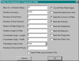
Again, I won’t go into
details about all of the fields, but you can see that there are many options.
Just leave the default values and pick the OK button to see what you get. You
should see the results box below.
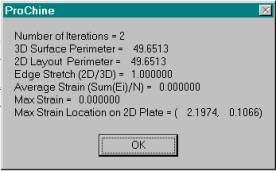
The program uses a
search technique to find the solution to the flattening problem. The default
condition is to make sure that the 2D perimeter of the pattern matches the 3D
perimeter of the 3D surface. The box also gives you some idea about the amount
of stretch in the middle of the plate. After you pick the OK button, you should
see something like what is shown below.
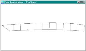
This shows the 2D
pattern of the top plate marked with all of the defined station locations.
Remember that some designers will change from defining stations to defining
frames (using PlaneCuts) during the later stages of design so that these
markings will show frame locations rather than station locations. The pattern
is rotated to minimize the amount of paper that would be used when the pattern
is cut out.
This view of the pattern
can be printed or plotted out at a scale factor, plotted out full size, or
output to various types of file formats to either bring to another location for
plotting or for CNC cutting.
To plot at a scale
factor or at full size, you need to go to the Options-Mod/Doc Definitions
dialog box, as shown below.
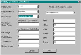
This example shows that
the program will use the defined scale factor and the defined scale factor is
one inch equals one foot. If you want to plot full size, then you need to
change the document units to feet. Then, the scale factor will be one foot
equals one foot. WARNING! Always use the File-Print Preview command to see if
and how the program will break the drawing into pieces (pagination) for
drawing. If you get the scale factor wrong, then the program might want to plot
out a thousand pages! The program “asks” Windows about the printer or plotter
that is attached to the system and what size of paper it is using. Then, the
program figures out how many pages are required to plot the drawing at the
selected scale factor. Note that the default print or plot size is to use
whatever scale factor will fit the entire drawing on your paper (one sheet).
For output to a file,
you need to use one of the options in the File-Data File Output submenu. The
most common one is to use the 2D DXF file output. Most CNC cutting systems can
read these files. If you are interested in doing this, then contact the place
that will be doing the cutting (or plotting) and see what software they have
and what transfer geometry file formats they accept.
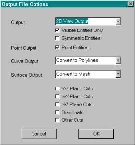
To output to a 2D DXF
file, first, make sure that the 2D pattern is shown in the current view window.
Next, select the File-Data File Output-DXF File Output command to see the
dialog box shown above. Now, make sure that the top field is set to “2D View
Output” rather than the 3D output option. This will guarantee that the program
will output the 2D view shown in the current view window. Once you select the
OK button, Windows will display a file output dialog box that you can use to
name the file and select the destination folder.
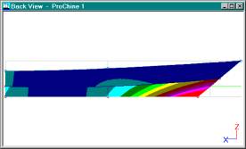
Well, we flattened this
plate, but how do we know if it is developable or buildable? We can use the Surf-K_Patch-Kpat
All command to turn on the display of the Gaussian curvature. If you select
this command and redraw the screen, you will see the following.
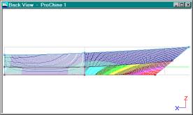
The dark blue indicates
a Gaussian curvature of zero, which means that that portion of the hull is
perfectly developable. (Gaussian curvature is a way of calculating how much
double curvature a surface has.) If the Gaussian curvature is zero, it means
that the surface has at least one direction that is flat at that point. As the
colors change to light blue, to green to yellow, and then to red, the amount of
double curvature increases. We have found that a boat is buildable if the
colors remain in the dark blue, light blue or light green regions. This means
that (within reason) you can twist or torture(?) the plate material to fit.
Please don’t hold us to this criteria, since everything depend on the type of
material, its thickness, and its dimensions. We usually tell people that if
there is any question at all, build a small model to see if everything will
fit. This is especially important if you CNC cut out both the frames and the
plates. You may wish to leave extra scrap material along one of the edges of
the plate. (See our other article that goes into more detail about this
developable vs. buildable question.)
Note that this picture
isn’t filled in completely. This is because the Gaussian curvature calculation
is done for each pixel of the boat and we wanted to make sure it is reasonably
fast. If you want to see what it would look like filled in completely, then
select the Surf-K_Patch-Kpat Options to see the dialog box below.
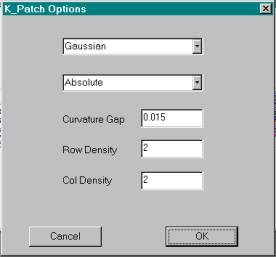
Change the Row and Col
Densities to 1 and select the OK button. You may have to use the View-ReDraw
View command to see what is shown below.
As you can see, it looks
better, but takes longer to draw. Note that the top plate is almost perfectly
developable, but there is a good amount of double curvature in the front end of
the bottom plate. If you are trying to create a developable boat, then you
would have to change the shape of the bottom surface and recheck with the
Gaussian curvature display. Since the Gaussian curvature cannot be dynamically
redrawn as you are dragging points on the surface, then you may want to look
into our “ruling line” method for creating developable surfaces. That technique
allows you to dynamically see the amount of twist in the surface while you are
dragging or moving the edit points. (See the other ruling line tutorial.)
If you use the develop
plate command on the step surface, this is what you will see.
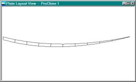
If you looked at the
Gaussian curvature of this surface, you would see that it was developable and
this pattern should be accurate.
This is the result of
developing the bottom surface.
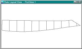
It can be done, but you
wouldn’t want to use the results, since it requires a lot of stretching. Just
because the program can flatten the 3D surface into a 2D pattern doesn’t mean
that you want to use the result. [I can, however think of one exception.
Perhaps you are trying to cut out some very stretchy material that you want to
use to protect the bottom of the hull.] In any case, we have to leave it up to
you to decide when to use a particular 2D pattern.
Before I end this
example, I want to make sure you know that the program created a deck surface
in the CreateBoat process. It was a simple straight across surface and it was
turned off. If you select the Surf-Draw All Surfaces command and turn on the
Render View, you should see something like what you see below.
Thank you for going through
this tutorial. Hopefully, it hasn’t been too long (or too short) or boring.
There are other tutorials and articles that can continue on from here. Feel
free to contact us if you have any questions or comments.