|
|
Features and Examples
1. Detailed curve and surface shaping and fairing
Most 3D modeling and CAD programs do not give you detailed curve and surface shape feedback and control. They might give you many ways to generate 3D surfaces and show their smoothness, but they give few or no ways to modify and smooth the resulting shape. You have to look at programs costing $10,000-$20,000+ to find the shape control capability that you find in ProSurf for just $395.
New Wave Systems, Inc. has been developing B-spline curve and surface software for over 15 years, applied to the design and shaping of curved boat and ship hulls, where shape control and smoothness are critical. Our shaping tools have evolved to the point where you can easily design and smooth anything. The reasons for this are that ProSurf provides you with 1) edit points that lie ON the curve AND surface, 2) dynamic overlay curvature fairing curves for both curves and surface rows and columns, 3) fine-tune shape commands, like our unique Ooch Point and Move% commands.
As many know, B-spline and NURB curves and surfaces define their shapes using vertex points that do not (necessarily) lie on the curve or surface. The original purpose of this was to make it easier to interactively create smooth curves and surfaces on the computer. The disadvantages of these vertex points are that 1) they make it difficult to accurately position the curve or surface, 2) these points are floating off the surface, and 3) their associated vertex mesh clutters up the screen. However, for every vertex point, there is an associated point that lies on the curve or surface. You might think of these as the interpolation points. Since 1985, New Wave Systems, Inc. has been allowing the use of these interpolation points to define and shape both B-spline curves and surfaces. (For surfaces, the edit points lie at the intersection of all principal iso-param rows and columns.) Everyone seems to be amazed at how easy it is to exactly control curve and surface shapes using these surface points. We also provide access to the official vertex points, but very few of our customers have ever needed to see a single vertex point or vertex mesh. Some might say that using interpolation points causes the curve or surface to be more bumpy or wiggly. This has never been a problem when the technique is used with our dynamic curvature fairing curve and our fine-tune Move% and Ooch Point commands.
ProSurf allows you to overlay a curvature curve on top of any curve or surface row or column. This curve magnifies all bumps and wiggles in the curve or surface row/col and marks all inflections. For a very small change in the edit point position, there is a large change in shape in the curvature curve. The magnification or sensitivity of the curvature curve can also be increased or decreased at any time. As you move/drag the edit point, the curvature curve gets dynamically recalculated and redrawn. This technique is very important for fairing surface rows and columns. Some modeling and CAD programs display "zebra" stripes, Gaussian curvature, or highlight lines to display the fairness of the surface, but none of these techniques are dynamically redrawn as you edit the shape of the surface. With our curvature curves for the surface rows and columns, you can turn on several at once and watch their shape change while you are dragging the edit points on the surface. We use displays like the Gaussian curvature color mapping to find surface areas that need further work using the overlay curvature curves.
|
|
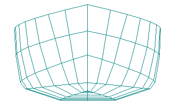
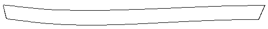
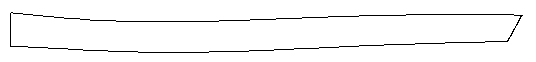
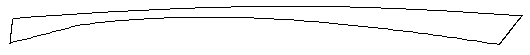
Notice that this long, narrow surface has edit points lying on the surface and notice the three overlaid, orange curvature curves for each of the rows of the surface. These overlay curves allow you to dynamically smooth the surface using our Move% and Ooch Point commands. Although ProSurf can display the true, smooth curvature curves, we find that these simple, polyline curvature curve approximations (one polyline point per edit point) work best for most situations. Turning on multiple curvature curves at once allows you to make sure that all rows have the same curvature shape. If you are shaping a surface with more than a few rows or columns, these row/col curvature curves are an absolute necessity if you want complete control over the shape of the surface. Other programs may provide automatic smoothing tools, but they come only at the expense of the loss of detailed shape control. You should not let these smoothing tools control the shape of your design.
As an extra check of the fairness of the surface, you can also display an accurate (by pixel) color mapping of the Gaussian curvature of the surface, as shown below.
|
|
The last capability that is needed is some way to perform fine-tune curve and surface shape changes. If you try to edit a curve or surface using the regular Move Point command, the curvature curve will change wildly in shape, even if you move the point by a few pixels. One solution is to zoom in on the area you wish to edit, but then, the curvature curve will be too large to be visible and you really cannot see what you are doing. We solved this problem by implementing the Move% and Ooch Point commands. The Move% command works just like the Move Point command except that the edit point only moves 1/100th of the distance towards the cursor point. The Ooch point allows you to move any edit point in any direction by some very small predefined distance. This means that you can perform detailed fairing with the curvature curve turned on without having to zoom in close. This keeps zooming in and out to a minimum. You would just Move% the edit point and watch the dynamic change in the curvature curve.
Our use of interpolation points, dynamic curvature curves, and fine-tune shape commands have proven themselves over the last 15 years and form the basis of our detailed curve and surface shaping toolbox.
2. Dynamic constraint relationships between geometry
In the boat design world, a common shape that has to be modeled is a chine hull consisting of two or more surfaces joined edge to edge. These multiply-connected surfaces are called polysurfaces in some 3D modeling programs. Amazingly, most modeling and CAD programs do not let you edit these shapes unless you "explode" or disconnect the surfaces at their edges. The surfaces will then separate if you move one of the edge points! This is completely unacceptable for shaping chine hull boats - AND for shaping most other types of objects where surfaces meet.Long ago, New Wave Systems, Inc. solved this problem by allowing surfaces to remain tied or "bonded" together along common edges while allowing the full range of editing commands. If you move an edit point on an edge between two surfaces, then both surfaces get updated dynamically. This is done by defining constraints or relationships between geometric objects. These relationships are optional and are independent of the definition of the geometric entities. This means that you can add or delete these relationships when necessary.
We have expanded this geometrical relationship idea to cover many different types of constraints - fix a point to a curve, fix a point relative to another point, fix a point to a surface, bond surface edges, fix a curve to a surface, and fix a surface edge to the middle of another surface. (The constrained points are edit points on the curves and surfaces.) These are dynamic constraints. This means that when you move a point on one entity, all related or constrained entities update dynamically at the same time. It is also an open-ended technology - we can easily add more and more constraints in the future.
The unique aspect of our technology is that the constraints are independent of the geometry and are optional. They can be added or deleted at any time. We feel that this is very important. Some 3D modeling and CAD programs force constraints upon your model whether you want them or not. This may make the modeling process more difficult, especially if you have to go back and make major changes to your model. With our technique, you can apply the constraints only when necessary, or if you need to make major changes to your model, we allow you to un-constrain the model without affecting the shape or deleting any of the geometry.
ProSurf also has the ability to mark a curve attached to a surface as a trimming curve for the NURB surface. You can drag the edit points on the curve and watch the trimmed surface dynamically update itself. You can even turn on the overlaid curvature curve for the trim curve to use for fairing. Most all other trimmed NURB surface modelers (even the expensive ones!) force you to un-trim the surface, redisplay the original curve, edit the curve shape, and then re-trim the surface by projecting the curve through the surface. This is not very convenient for fairing or if you need to have other geometry constructed based on the shape of the trim curve. Our attached curve method for trimming will also work for trim curves that cannot be created by simply projecting a curve through a surface.
 |
NURB surface showing attached NURB curve with edit points. This curve was created and attached to the surface in one step.
 |
NURB surface after trimming with attached NURB curve
 |
NURB surface after dynamically moving edit point on NURB curve
 |
NURB surface after moving edit point on the NURB surface
The NURB curve is relationally attached to the NURB surface so that you can dynamically drag any edit point on the curve or surface. Remember that a "curve" in ProSurf can consist of both curved and straight line segments. You can also turn on the overlaid curvature curve for this attached curve.
3. Combination polyline and curve entities
In most 2D or 3D design programs, curves and polylines are separate entities. This is done as a convenience for the programmer, not the user. There are many times when the designer needs to combine both of these shapes together or to convert one shape to another. When the designer is creating a 2D or wireframe shape there is often a need to insert and delete points and to change part of a curve back and forth between a curve shape and a polyline shape. Designers do not want to be forced to deal with multiply-connected polyline and curve entities. For example, what if you want to insert a knuckle or hard point in the middle of a curve. Most programs would have you split the curve into two separate curve entities that are joined at that hard point. This process could consist of several steps.
ProSurf avoids these problems by allowing a "curve" entity to consist of both polyline and curve segments. (Note that this is not done by doubling up on knot values or vertex values.) Each edit point that defines the combined entity includes an indicator that says whether it is a curvefit point or a polyline knuckle point. This means that the user doesn't have to worry about connecting or splitting separate curve or polyline entities. If you want to change an edit point to/from a curvefit point from/to a polyline point, you just have to pick the point with the knuckle (toggle) command. You can even create one of these combo curve-polylines by picking the input positions using the 'c' (curve) or the 'k' (knuckle) keys.
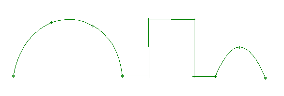 |
This combination of polylines and curves is just one "curve" entity in ProSurf. It was defined all at once, using just one curve input command.
This combination curve/polyline entity might seem like a minor capability, but it can save you a lot of time and aggravation. Many that have used our technique find it is the easiest and fastest way to create 2D and 3D wireframe graphics, including those techniques provided by the top selling graphic arts programs.
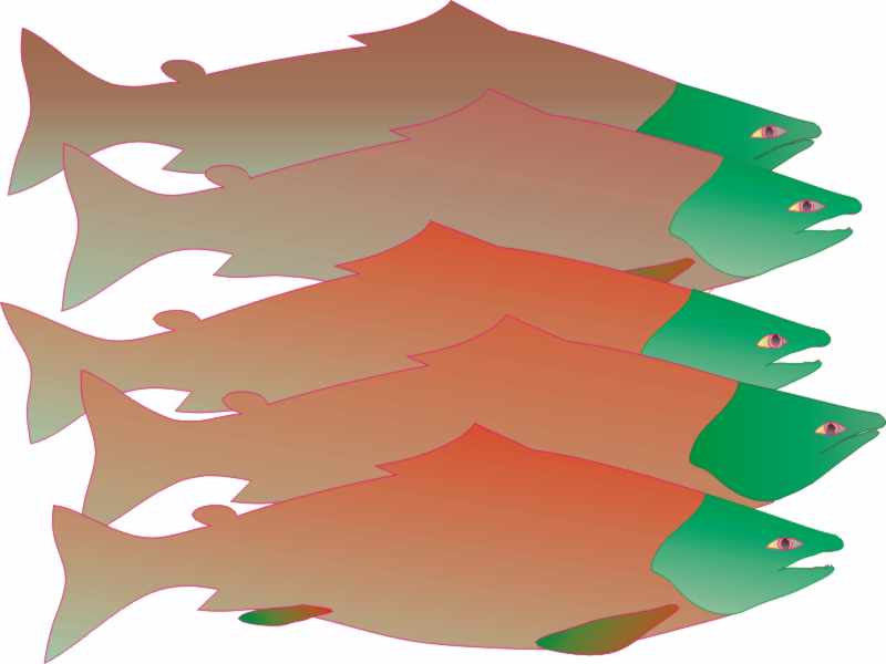 |
Salmon graphic created in ProSurf and colored in Corel Draw by Mark Ervice
"... Most importantly, I am convinced more than ever that your program would be the most welcome add-on to traditional drawing programs. I have been using Corel Draw for about 3 months now and have tried trial versions of FreeHand, Canvas, and Illustrator. None of them offer the fine control of shape as does your program, even though they purport to. I am continually amazed at the versatility of your program." ... Mark Ervice
4. Developable and expanded surfaces
One of the things we are trying to do with ProSurf is to provide tools that are not found in many other 3D modeling and CAD programs, except, perhaps, as expensive add-ons. For example, ProSurf includes commands to create and layout both developable (flat, cylindrical, conical) and expanded (doubly-curved) surfaces. Many surfaces need to be constructed from flat material, like plywood, aluminum, and cloth, even if the material has to be forced or stretched into shape. ProSurf provides commands that help you create these surfaces and lay them out flat so that they can be cut out by numerical control.
Creating developable surfaces is tricky because it is rarely necessary or practical to create perfectly developable surfaces. All materials stretch to one extent or another which allows for a certain amount of twist. It depends on the properties of the material, its size, and its thickness. ProSurf helps with this problem by letting you define surface "ruling" lines between any two curves. These ruling lines are dynamically redrawn as you move the edit points on the two boundary curves. In addition, the ruling lines are drawn using colors that define the amount of twist in the plate in that location. The user can dynamically adjust the two curves until they achieve a good spread of ruling lines with an acceptable level of twist. A NURB surface can then be fit to the ruling lines to create a true surface that can be flattened. The flattened 2D plate shape can also be marked with cross-section trace lines.
ProSurf can also flatten any doubly-curved surface. It uses a finite element-like approach to accomplish this task and it also calculates all of the internal strains on the plate. Plate expansion is not a unique process. An infinite number of 2D shapes can be stretched to create the final 3D shape, depending on the equipment used and the skill of the operator. ProSurf allows you to find the 2D expanded shape that minimizes the sum of the internal strains on the 3D shape.
 |
 |
 |
 |
 |
 |
Delft 25 multi-chine vessel showing hull and 5 developed plates.
Courtesy of Sponberg Yacht Design
5. Airfoil shapes - create, fair and then skin into 3D shapes
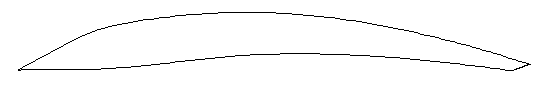
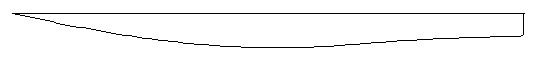
ProSurf gives you access to both the standard NACA 4-digit series of airfoil shapes and the UIUC database of 1000+ airfoil shapes. (http://amber.aae.uiuc.edu/~m-selig/ads.html) These shapes can be read into ProSurf and automatically curvefit. You can pick the location of the leading edge and then drag and stretch and rotate the trailing edge dynamically on the screen. Once defined, it is a simple process to use our curvature curve and fairing tools to smooth the foil to any level of accuracy - it takes only a minute or two. To create a full 3D airfoil, you can repeat this process for both the root and tip foil shapes and then skin a surface between the two. You can even add additional foil sections in the middle before skinning. If the 2D foil sections have been pre-faired, then you can be sure that the final 3D surface is fair.
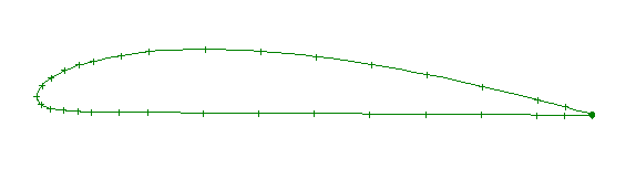 |
This is the Clarkz.dat airfoil from the UIUC database. It was input, curvefit and faired in just minutes.
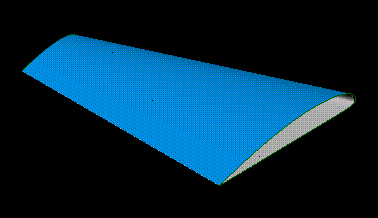 |
This is a 3D airfoil using the Clarkz airfoil from above. The 2D airfoil shape was copied, moved, and scaled to create the tip shape. Then the skin command was used to create the 3D airfoil. This took just a minute or two to complete.
6. Extrude combined curves and polylines into bonded, editable polysurfaces
As discussed above, ProSurf allows you to define combination curves consisting of both curve and polyline segments. You can extrude, sweep, or skin this type of combination curve into one or more 3D surfaces. For example, if you have a "curve" consisting of 1 polyline section and 2 curve sections, ProSurf allows you to extrude or sweep this shape into multiple, bonded surfaces. Each segment of the polyline can be extruded into a surface, or you can specify that the entire polyline section should be curvefit with one surface. The resulting surfaces have bonded edges that can be edited without separation.
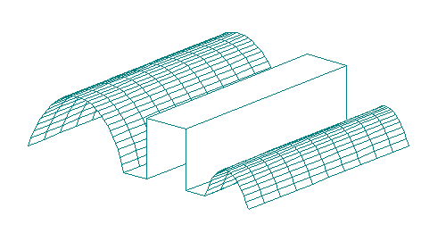 |
These 7 surfaces were created with one command by extruding the "curve" consisting of two curve sections and one polyline section. The edges of the surfaces are "bonded" and can be edited without separation.
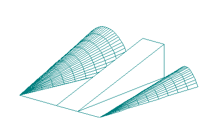 |
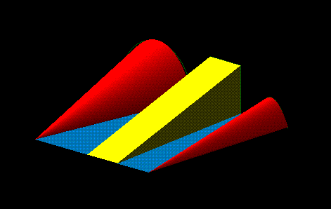 |
These pictures show two views after the bonded surfaces were edited without separation. This change took about a minute to do.
7. Shelling (offset) polysurfaces with surface trimming or extension
ProSurf can offset or shell multiple NURB surfaces into new NURB surfaces that are trimmed or extended and then bonded. Shelling is not an exact process, but ProSurf creates usable, editable offset surfaces. An offset surface is created by projecting each edit point normal to the surface by the desired amount. The offset surface edge points are then adjusted to re-connect with the offset edge points of any adjacent surfaces. These points are then fit with a NURB surface and the edges are bonded. You can then use the skin command to close off the open sides and edges of the polysurface to create a complete, accurate 3D shelled solid.
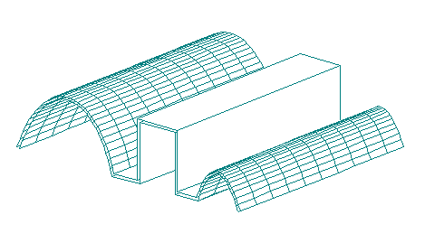 |
This picture shows the results of shelling multiply-connected surfaces, with trimming or extension of edges. The offset surfaces are NURB surfaces with bonded edges, which means that they can be edited just like the main surfaces.
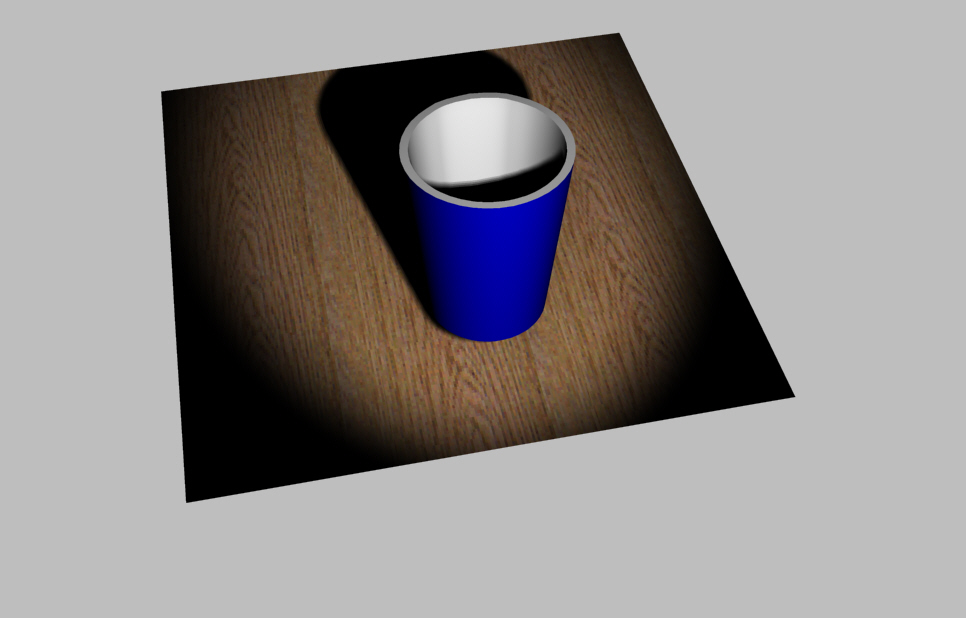
ProSurf allows you to automatically create full 3D closed, editable (bonded), solids of a variety of shapes, like triangle solids, box solids, wedge solids, cylinders, cones, spheres, ellipsoids, and sphere and ellipsoid arc sections. These shapes can also be a solid shape or a hollow shape with a user-defined thickness. If a hollow (with thickness) solid is created, it can be optionally closed or capped off. For example, with one command, you can define a truncated conical cup that is closed off at the bottom and open at the top (see picture below). The solid has the same thickness all around and all surfaces are closed and bonded. This means that the object can be edited using any of the points lying on the surfaces and still maintain connections to all other surfaces.
 |
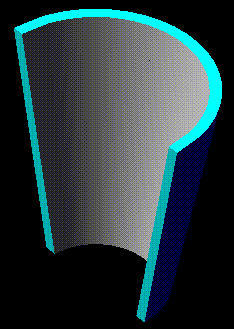 |
You can even define a limited range of angles for the cylinder, cone (see above), spherical and ellipsoid (see below) solids. Above is a 180 degree hollow, truncated cone with thickness and capped off and bonded edges to form a closed, editable 3D solid.
 |
9. Very low price - only $395 US - direct
We develop all of our own software and sell it directly to you. There are no dealer markups or hidden costs or royalties that we have to pay. Our slogan is "3D For All" which means that we will keep the price low and make the program as powerful and as easy to use as possible.