In spite of what you may have heard, these two statements are true:
1. There is no mathematical definition of fairness.
2. The fairness of a curve or surface is based on human interpretation and judgement.
This does not mean that everyone would disagree on the fairness of a curve or that there are no mathematical tools to use to check for bumps and wiggles. It just means that there are no good ways to automatically fair a curve or surface by computer without some form of human input.
Let's start by examining the traditional fairing process on the drafting board or on the loft floor. The first tool of fairing is the large size of the drawing and the use of the human eye. Given a large enough drawing, the human eye can easily pick up subtle shape changes (within building tolerances). There is nothing like putting your head down near the drafting table and sighting down a waterline or diagonal.
For the traditional lines drawing process, there are two interrelated processes taking place: fairing and matching up the three different lines views: profile, plan, and section views. Matching up the three lines views refers to the process of matching up the shape of the different lines in the different views. For example, the half breadth (width) of a station at a particular waterline in section view must match the half-breadth of that waterline, at that station, in plan view. This matching up of the three views is under the complete control (is the responsibility of) the designer or the loftsman. Many times a designer will fair a station or a waterline only to find that the three views no longer match and define a legal boat. Producing a usable lines drawing involves matching up the lines in all three views AND making sure that the lines are fair. This two-part process is what makes lines drawing or lofting so difficult.
The following pictures describe the different lines of the boat and the two standard types of lines drawings.
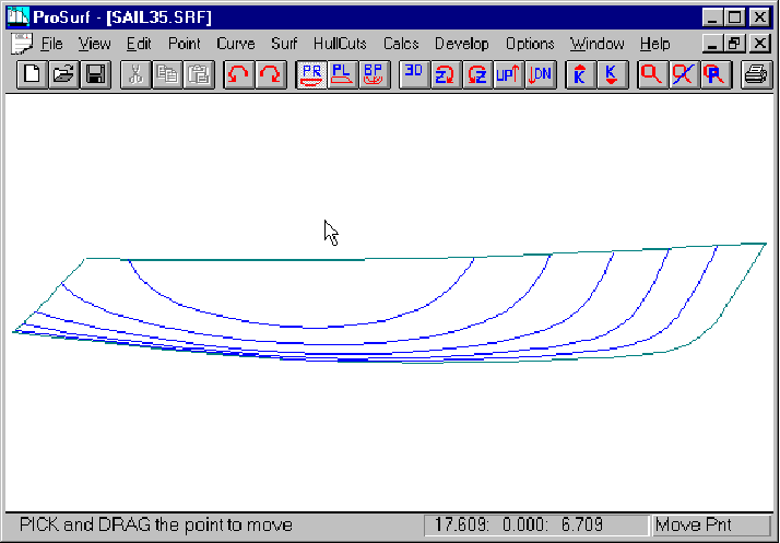
This picture shows a few buttocks of a sailboat hull. These hull cuts are defined by cutting the NURB surface with planes parallel to the centerline of the boat at various half-breadths. In ProBasic/ProSurf, you can define any number of buttocks at any location and the program will automatically "cut" and display their shapes.
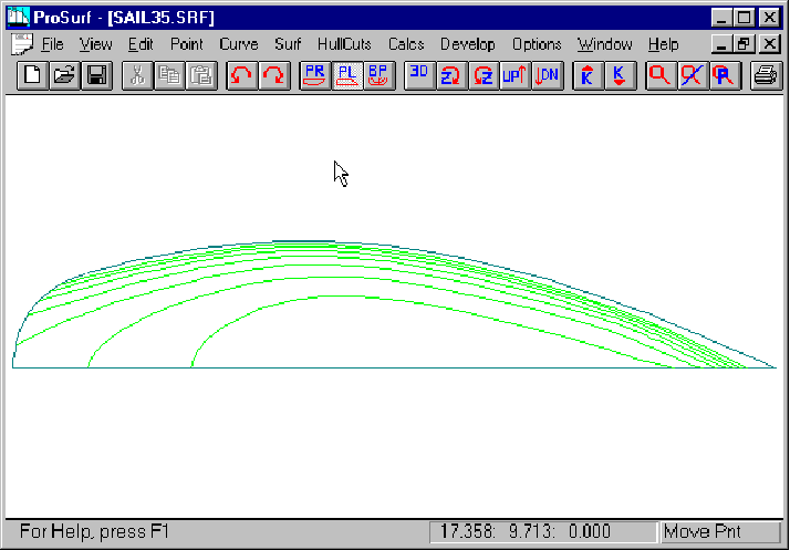
This picture shows a few waterlines of a sailboat hull. These hull cuts are defined by cutting the NURB surface with planes parallel to the design waterplane of the boat at various distances above the baseline. In ProBasic/ProSurf, you can define any number of waterlines at any location and the program will automatically "cut" and display their shapes.
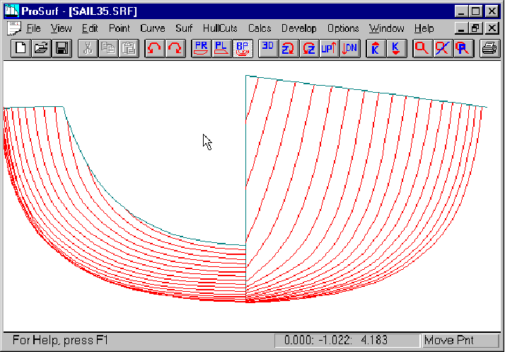
This picture shows a number of stations of a sailboat hull. These hull cuts are defined by cutting the NURB surface with transverse planes at various distances from the forward perpendicular (X=0). In ProBasic/ProSurf, you can define any number of stations at any location and the program will automatically "cut" and display their shapes.
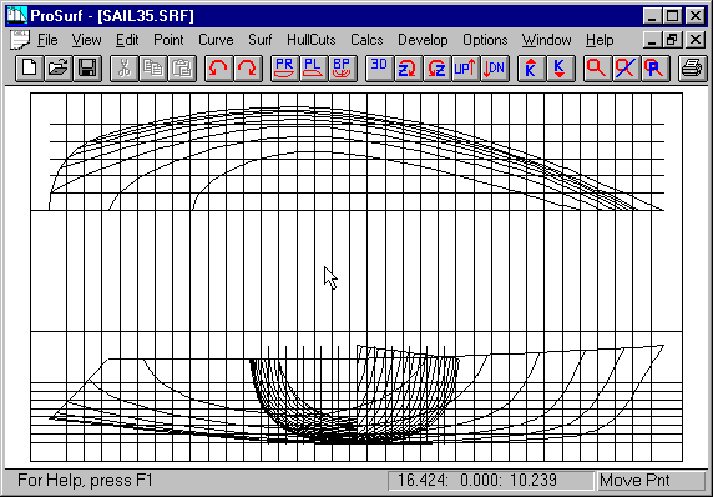
This is a lines drawing automatically created and drawn by the program. It is called an overlay format, because the body plan or sections of the boat are drawn on top of the profile view of the hull at amidships. The advantage of this format is that it takes up less space, but the disadvantage is that the lines cannot be clearly seen for small drawings. This format is commonly used for large ships with a long parallel middle-body. Since the buttocks of the ship are constant near amidships in profile view, they do not interfere with the body plan if it is placed at amidships.
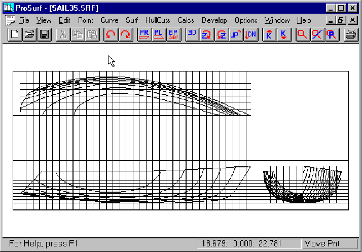
This is a lines drawing automatically created and drawn by the program. It is called a separate format, because the body plan or sections of the boat are drawn to the right of the profile view of the hull. The advantage of this format is that the lines are more clearly visible, but the disadvantage is that the drawing takes up more space. If you are dealing with a fixed plotter paper size, then the drawing must use a smaller scale factor that the overlay lines format.
Using a computer program for defining and fairing a boat, however, removes the matching problem. This is because the program defines the complete surface mathematically using something akin to a stretchable rectangular-like spline membrane. If you pull the surface in one direction, the surface is updated in all three views. The program can "cut" the surface at any time to determine the shape of any of the lines, and there is a guarantee that all of the lines match in all of the views.
The only thing that a computer boat design program cannot do is to automatically shape and fair the boat. It doesn't know what a good boat shape is and it doesn't know what a fair boat is. Therefore, it is up to the designer using the program to define a proper boat shape and make sure that the shape is fair. The big benefit of the computer program is to eliminate the lines matching problem. This makes it much more easy for people to design accurate boat hull shapes (the lines are guaranteed to match in all views).
Some boat design programs insist that there is no need for fairing the boat because it is automatically fair. This can only be true if the program severely limits the range of hull shapes that can be defined. It is kind of like defining a boat using a batten and only three ducks. It is virtually impossible to create an unfair line with this limitation, but, it is also impossible to create anything but the most simple of shapes. With a computer program, the tools may be fancier, but the limitation is the same. You don't get automatic fairness for free.
If the computer program does not fair the boat, then how do you fair a boat on a small computer screen? For traditional drafting and lofting, you can use a number of the following techniques:
1. Examining a hull curve by eye
2. Fore-shortening the drawing in the longitudinal direction
3. Lifting a duck from the batten to "relax" the curve shape
The most important fairing technique is examining the lines by eye. On a small computer screen, this is impossible. It is aggravated by the "jagged" display of the curves due to the resolution of the screen. Some designers hope for a large (6 foot) flat panel computer screen to replace their traditional drafting board, but it is quite unlikely to see this in the near future or for any reasonable cost.
If you cannot use your eye to fair a hull on the computer screen, what can a boat design program do? Although there is no mathematical definition of fairness, many feel that the use of second derivative or curvature techniques hold the solution. These two techniques are variations of each other since curvature is based on the second derivative of a curve or surface. What these techniques do is to magnify and define all of the bumps, wiggles, and inflection points of a curve or surface so that the designer (program user) can alter the hull shape to achieve his/her own criteria of fairness. What would be an invisible unfairness of the lines of the boat on the computer screen, become clearly visible when using one of these derivative techniques. All boat design programs approach this fairness magnification in different ways and each technique greatly influences how easy it is to fair a hull.
ProBasic and ProSurf use a dynamic curvature curve overlay technique which is felt to be the easiest and fastest fairing technique to learn and use. It can be applied to both NURB curves and NURB surfaces. A related technique for surfaces is the surface coloring of the hull based on one of its surface curvatures: Gaussian or mean curvature.
This tutorial will first discuss the shaping and fairing of curves using the curvature overlay technique. Then it will discuss the shaping and fairing of surfaces using both the curvature overlay technique and the Gaussian surface curvature display.